
Privacy statement: Your privacy is very important to Us. Our company promises not to disclose your personal information to any external company with out your explicit permission.
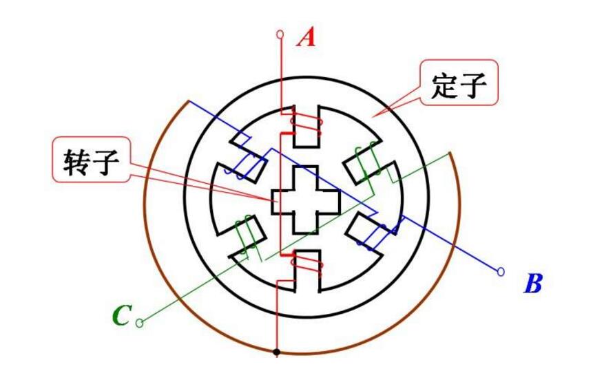
When a current flows through the stator windings, the stator winding generates a vector magnetic field. The magnetic field will drive the rotor to rotate an angle so that the direction of a pair of magnetic fields of the rotor coincides with the direction of the magnetic field of the stator. When the stator's vector magnetic field rotates an angle. The rotor also turns an angle with the magnetic field. Each time an electric pulse is input, the motor rotates an angle forward. The angular displacement it outputs is proportional to the number of input pulses and the speed is proportional to the pulse frequency. By changing the order in which the windings are energized, the motor will reverse. Therefore, the number of control pulses, the frequency, and the sequence of energization of the motor phases can be used to control the rotation of the stepper motor.
Commonly seen types of motors have iron cores and winding coils inside. Windings have resistance, and power will produce losses. The loss is proportional to the square of the resistance and current. This is the copper loss we often say. If the current is not a standard DC or sine wave, it will also produce harmonic losses; the core has hysteresis. The eddy current effect also produces losses in an alternating magnetic field. Its magnitude is related to material, current, frequency, and voltage. This is called iron loss.
Both copper loss and iron loss are manifested as heat, which affects the efficiency of the motor. Stepping motors generally seek positioning accuracy and torque output, the efficiency is relatively low, the current is generally large, and the harmonic components are high, the frequency of the current alternating changes with the speed, so the stepper motor generally has a heating condition, and the situation is more general Severe AC motor.
Three stepper motor circuit diagram circuit one: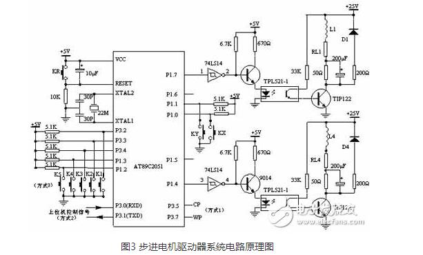
RL1 ~ RL4 in Fig. 3 are the internal resistance of the winding, 50 Ω resistance is an external resistance, act as the limit current, it is a component that improves the time constant of the circuit. D1 ~ D4 are freewheeling diodes, so that the back EMF generated by the motor windings is attenuated through the freewheeling diodes (D1 ~ D4), thus protecting the power tube TIP122 from damage.
Connecting a 200μF capacitor in parallel with a 50Ω external resistor can improve the front of the current pulse injected into the stepper motor winding and improve the high frequency performance of the stepper motor. The 200Ω resistor in series with the freewheeling diode can reduce the discharge time constant of the loop, make the trailing edge of the current pulse in the winding steeper, and the current fall time becomes smaller, which also plays a role in improving high frequency operation performance.
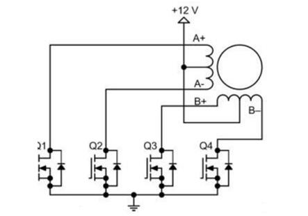
Circuit diagram 2:The driving circuit of the bipolar stepper motor is shown in the figure. It uses eight transistors to drive two phases. The bipolar drive circuit can drive four-wire or six-wire stepper motors at the same time. Although four-wire motors can only use bipolar drive circuits, they can significantly reduce the cost of mass production applications. The number of transistors in a bipolar stepper motor driver circuit is twice that of a unipolar driver circuit. Four of the lower transistors are usually directly driven by a microcontroller, and the upper transistor requires a higher-cost upper driver circuit. The transistor of the bipolar driving circuit only needs to withstand the motor voltage, so it does not need the clamping circuit like the unipolar driving circuit.
The stepping motor can not be directly connected to the work frequency AC or DC power supply, but must use a dedicated stepping motor driver, as shown in FIG. 2, which is composed of a pulse generation control unit, a power drive unit, and a protection unit. The two units surrounded by the dotted line in the figure can be implemented by microcomputer control. The direct coupling of the drive unit to the stepper motor can also be understood as the power interface of the stepper motor microcomputer controller.
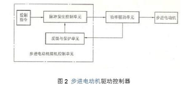
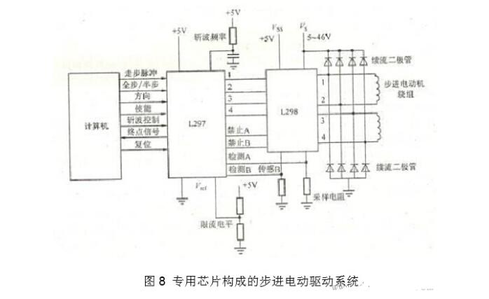
FIG. 8 is a stepping motor drive system having a constant current chopper function, which is constructed using L297 (circular distributor dedicated chip) and L298.
The stepper motor has no encoder. If you want to add an encoder to the stepper motor, you can use a biaxial extension of the stepper motor and add an encoder to the rear shaft.
The stepper motor is the implementation of the original, the encoder is a feedback system, the encoder is used with a stepper motor, and the PLC is used to control its operation. In principle, the PLC sends a pulse command to the stepper driver. The driver supplies the stepper motor with the corresponding current to make it run. When the encoder detects that the stepper motor has reached the required position, it will feedback the signal to the PLC. PLC installation The feedback signal stops sending the pulse signal to the stepper driver. When the stepper motor has no power supply, it will stop running immediately. (Servo motor is such a device). Actually, the encoder will continuously feedback the current position to the PLC. PLC will compare the feedback value with the target value to adjust the rotation angle of the rotor.
Of course, it will not stop, after the stop is not your desired position, this depends on whether the motor brake device? Of course, at low speed, the feed accuracy can be generally satisfied.
Another method is to calculate the number of pulses needed to feed the stepper motor in advance, and then use the PLC to program so many pulses, the stepper motor stops, and the encoder feedbacks the motor position at this time to form a semi-closed loop control. In addition to high-speed positioning, the PLC program can set the motor to decelerate the feed when it reaches the position quickly, which can satisfy the positioning accuracy.
Stepping motor plus coding is a bit ridiculous, it is a waste of resources; because the stepper motor can not respond in real time, there must be an acceleration and deceleration process;
Example: Oriental stepper motor with harmonic reducer, reduction ratio 100:1 Step angle: 0.0072°, want to add an encoder to prevent losing steps, etc. Here are the methods:
Answer: In principle, it is also possible to mount the motor on one end of the screw and the other end to install the encoder. However, this will be affected by the accuracy of the reducer, and misjudgment of lost motion may occur. The encoder is preferably a dual-axis motor. The encoder is added to the rear of the motor. Servo motors do this unless you have special use or limitations (no double-out). It is generally possible to process 2500 lines. Too high lines is also a waste.
In addition, the resolution of the encoder is approximately the same as the resolution of your stepper motor. If the segmentation on the drive is high and you only want to detect if you have lost your steps, the resolution of the encoder should be the same as or slightly higher than the resolution before segmentation.
The meaning of stepper motor plus encoderAlthough the stepper motor can be precisely controlled devices, but it is open-loop, need to install an encoder to achieve closed-loop feedback control; and can measure stepper motor out of step and rotation or speed, for dynamic speed control. For this statement, Xiao Bian think that the first point of open-loop control requires the encoder to achieve closed-loop feedback is still understandable, because Xiao Bian himself in use, and occasionally because of stepper motor line connection is not good, resulting in stepping The motor did not work properly. For the speed control of the second stepping motor, it is not very necessary because the speed can be realized by controlling the pulse frequency of the stepping motor, and it is not necessary to use external feedback.
Wyślij je do tym dostawcy

Privacy statement: Your privacy is very important to Us. Our company promises not to disclose your personal information to any external company with out your explicit permission.

Fill in more information so that we can get in touch with you faster
Privacy statement: Your privacy is very important to Us. Our company promises not to disclose your personal information to any external company with out your explicit permission.